Built to Print: Guidelines for 3D Printing
Amit Pal2025-01-28T08:39:21-06:00Arctos and the larger TyRex family have spent years developing our 3D design and production processes to great effect. Through the introduction of additive manufacturing, we’ve avoided supply chain issues, reduced the weight and unit prices of products, and quickly iterated on designs in ways once thought impossible. In this time spent developing, we’ve come to rely on a set of design guidelines that help keep our printed components as functional as possible, which we’ll list below.
Gradual Transitions
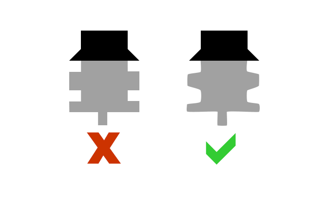
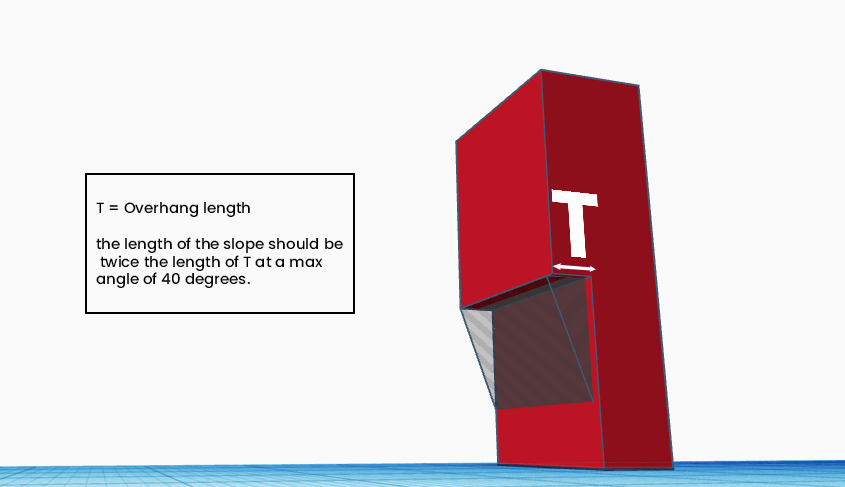
Regardless of printing technique, every design is divided into “slices” or layers that the printer will add to, whether through layering filament or continuously curing resin. Problems can occur if the changes between slices are too dramatic, like a large, 90 degree step between layers. Large, abrupt changes can lead to warping, witness lines (marks left after separation from support) and eventual stress and failure of the part. To avoid this we advise clients to employ ramps, curves, fillets, or chamfers in their design geometries. As a refresh, fillets refer to the rounding or sloping of corners and chamfers are the opposite, a straight graduation between two joining edges. Regardless of what method you use to reduce the amount of change between slices, a good rule of thumb is to not exceed 40 degrees of overhang.
| Features | RPU 70 | RPU 130 | MPU 100 | EPU 40 | EPU 41 | FPU 50 | CE 221 | EPX 82 | EPX 86FR | IND 405 | PR 25 | UMA 90 | SIL 30 |
|---|---|---|---|---|---|---|---|---|---|---|---|---|---|
| Max Overhang for Carbon M Printer (mm) | 2.0 | 2.0 | 2.0 | 1.0 | 1.0 | 2.0 | 3.0 | 2.0 | 2.0 | 2.0 | 3.0 | 3.0 | 1.0 |
Wall Thickness
When it comes to the wall thickness of a part, a few rules are obvious, such as reducing unnecessary thickness to cut down on material cost and speed up print time. There are considerations to determining wall thickness beyond speed and material cost, one being uniformity. Designers should strive to keep uniform thickness across different faces to avoid stress and warpage during post-processing.
Another factor to consider is the thickness of unsupported walls, or walls that are connected to the over piece on only one face. The necessary thickness of the wall is largely dependent on how tall the wall is and the material used. Adding support walls is recommended if the wall needs to be thin because supported walls can afford to be much thinner.
Overhangs
Mentioned earlier, overhangs are unsupported features that project out and over other features in your part. The amount that an overhang can extend from a part is influenced by the print method, printer, and material used. DLS processes, which are used by Carbon printers, allow for much larger overhangs when compared to other printing processes. Below is a chart showing how even within the Carbon family, printer and material choices affect the maximum distance of an overhang.
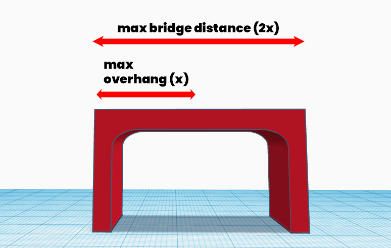
Bridges play by a similar set of rules, but are allowed to be designed longer because they are supported on both ends instead of just one. Typically, a bridge can only be twice as long as an overhang for a given material.
Unsupported Angles
While overhangs and bridges connect to the larger part at or close to 90 degrees, similar rules exist for features that extend out at more acute angles. Again, material choice largely determines how acute an unsupported angle can be, along with the thickness of the protruding part.
| Features | RPU 70 | RPU 130 | MPU 100 | EPU 40 | EPU 41 | FPU 50 | CE 221 | EPX 82 | EPX 86FR | IND 405 | PR 25 | UMA 90 | SIL 30 |
|---|---|---|---|---|---|---|---|---|---|---|---|---|---|
| Unsupported Angle Horizontal (degree) | 30 | 40 | 40 | 40 | 40 | 35 | 40 | 40 | 40 | 40 | 30 | 30 | 40 |
Positive Features
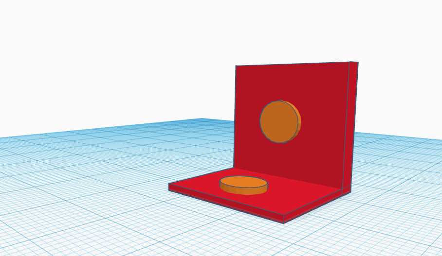
Positive features refer to non-wall features that protrude from the wall. The maximum level they can protrude is determined by the material used and also by the orientation of their protrusion. If the feature extends up from the horizontal XY axis, that maximum is much higher than a part printed out from the vertical Z axis. There are minimum levels of protrusions as well that are influenced by the resolution of the printer and the post production processes used.
| Features | RPU 70 | RPU 130 | MPU 100 | EPU 40 | EPU 41 | FPU 50 | CE 221 | EPX 82 | EPX 86FR | IND 405 | PR 25 | UMA 90 | SIL 30 |
|---|---|---|---|---|---|---|---|---|---|---|---|---|---|
| Recommended Max on XY (mm) | 0.4 | 0.3 | 0.4 | 0.5 | 0.75 | 0.5 | 0.4 | 0.3 | 0.5 | 0.5 | 0.6 | 0.4 | 1.0 |
| Recommended Max on Z (mm) | 0.2 | 0.3 | 0.2 | 0.2 | 0.3 | 0.2 | 0.2 | 0.2 | 0.2 | 0.2 | 0.2 | 0.2 | 1.0 |
Holes, Blind Holes, and Clearance for Mating Parts
When designing parts with holes, designers should take precautions similar to those in injection molding. Orientation plays a major part in how small a hole should be, again with emphasis on the material being used. Depending on the printing and post processing method used, oversizing may be advised to account for shrinkage during curing.
Blind holes, or bosses, are holes that do not extend through the entire part and should generally be avoided. These hidden areas allow resin to pool in places that cannot be removed in post-processing. If a blind hole must be used, be sure to connect it to a vent.
Similar to the attention needed when deciding cavities for insets and through holes, designers need to be aware of how their chosen material will react to curing after printing and design within the recommended clearance.
Venting
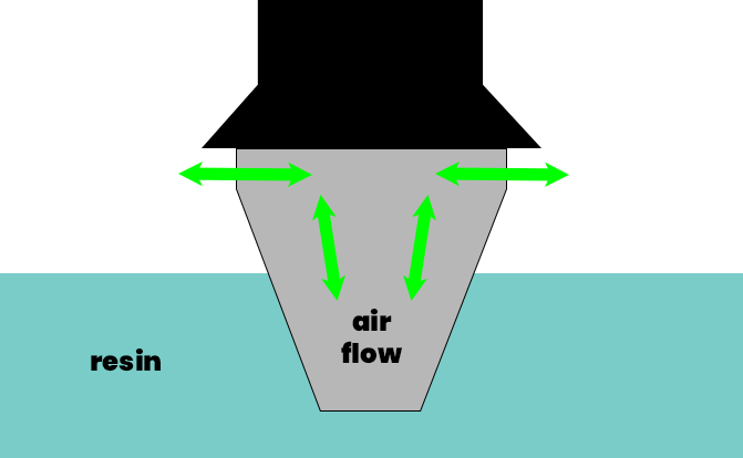
Venting is a necessary feature for parts being printed with resin. By placing vents close to the build plate, resin, solvent, and air can all pass freely during cleaning. Insufficient venting is the source of a lot of print failure and the size of vents will be dictated by the printer and resin used.
Inserts and Threads
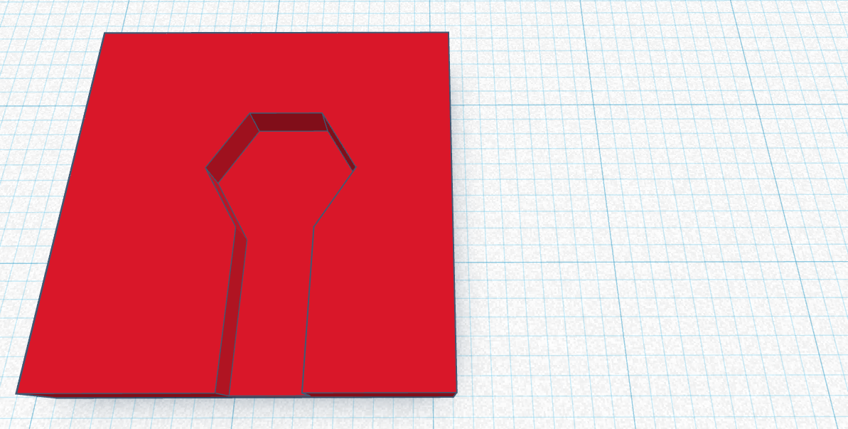
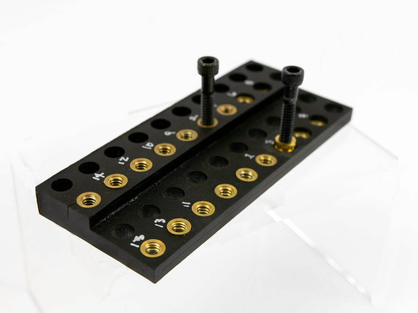
We’ve written before about the power of integrating metal into 3D printed polymer parts, and there are a few design choices that can optimize this integration. For example, cavities that will eventually hold a nut should be printed in the same pattern as the nut (e.g. a hexagon) to avoid rotational stress once the nut is inserted and used. However, designing with a bit of clearance to allow for some play is recommended.
High resolution printers like the Carbon line can print screw threads for end-use, but there are limits. The manufacturer recommends printing threads no smaller than M4 (0.7-mm pitch) and to print the threads with vents. Threads should also be printed parallel to the print platform for the best accuracy. Post-processing takes extra importance here to avoid warping and the threads will need to be chased with a tap, a tool used to cut female screw threads.
Engraving, Embossing, Text Sizes
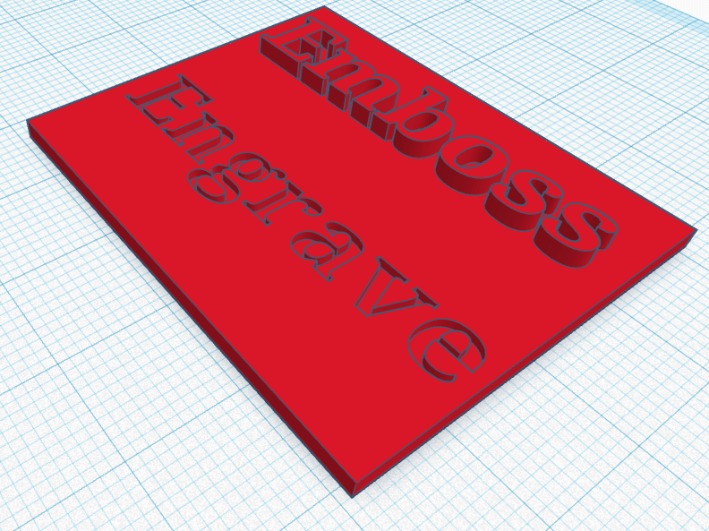
Embossed text protrudes from the part while engraved text is etched into the surface. Similar to positive features and holes, there are minimum values at which text should be embossed or engraved based on the material used. In addition to minimum height and depth, minimum text size should also be considered for legibility. Text should be printed perpendicular to the build platform (window facing) for the best resolution and quality.
| Features | RPU 70 | RPU 130 | MPU 100 | EPU 40 | EPU 41 | FPU 50 | CE 221 | EPX 82 | EPX 86FR | IND 405 | PR 25 | UMA 90 | SIL 30 |
|---|---|---|---|---|---|---|---|---|---|---|---|---|---|
| Engraving Depth/Embossing Height (mm) | 0.3 | 0.3 | 0.3 | 0.3 | 0.3 | 0.3 | 0.4 | 0.3 | 0.3 | 0.5 | 0.3 | 0.3 | 0.5 |
Conclusion
While additive manufacturing provides game-changing benefits to traditional manufacturing, there are many nuances to delivering a perfect design. Reach out today and learn about how our experienced team and design house can better help you realize the perfect engineered solution for your product.

